


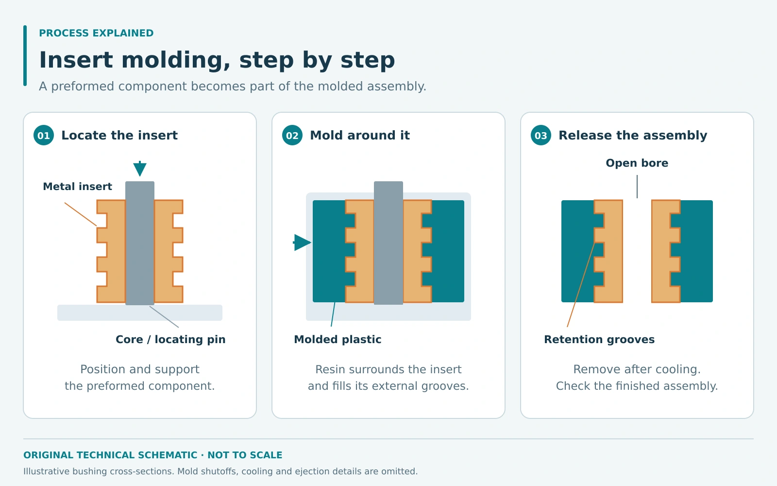
Insert molding combines a preformed component with an injection-molded plastic body. A threaded metal insert, electrical contact, bushing, or other component is positioned inside the tool before molding. Plastic then fills around selected areas of the insert, producing an integrated assembly.
The approach is useful when different materials serve different functions: metal can provide a reusable fastening surface or electrical connection, while plastic forms the surrounding housing. Success depends on how the insert is retained, supported, and inspected throughout production.
How the insert molding process works
- Prepare the insert and tool. Confirm the insert dimensions, condition, and orientation. The mold needs locating features that hold it in position and shutoff surfaces that protect areas where plastic must not enter.
- Load and locate the insert. An operator or automated handling system places the insert into its nest or onto a core pin. The loading method must reliably distinguish a correctly seated insert from a missing or misplaced one.
- Close, clamp, and inject. After the tool closes, molten resin flows around the insert. Its support must withstand the forces generated during filling without allowing movement that changes the finished geometry.
- Pack and cool. Pressure and cooling are controlled to form the plastic body. The selected process must protect the insert and produce the required dimensions around it.
- Remove and inspect. The mold opens and the assembly is ejected or removed. Checks may include insert position, exposed contact surfaces, thread cleanliness, and the mechanical performance of the joint.
Design retention into the assembly
Encapsulation alone does not guarantee a durable chemical bond. Many metal-to-plastic assemblies rely on mechanical engagement. Knurls, grooves, holes, or undercuts can give the solidified resin features to grip. SPIROL describes how molded-in insert features resist both rotation and pull-out in its threaded insert guidance.
Define the actual load case before selecting that geometry. A threaded insert may need to resist screw installation torque, repeated servicing, and axial force. An electrical contact may instead have strict positional and exposed-surface requirements. These are different design problems even when both use insert molding.
Review resin selection and the insert material together. The interface must tolerate processing conditions and the intended service environment. Where adhesion is important, confirm it by testing the proposed material pair and surface preparation rather than assuming compatibility.
Benefits and production limits
Insert molding can remove a separate assembly step and hold several components in a defined relationship. It can also place a metal function only where needed, while allowing the surrounding plastic geometry to integrate mounting or enclosure features.
Those benefits come with additional tooling and handling requirements. Insert supply variation, incorrect loading, or movement during filling can turn an otherwise acceptable plastic part into a rejected assembly. Loading time also contributes to production cost, and rejected parts may contain valuable inserts.
For threaded hardware, compare molding-in with post-mold installation. The appropriate choice depends on joint performance, resin, access for assembly, production quantity, and the complete manufacturing cost. The lowest tooling price is only one part of that decision.
An effective insert-molded assembly gives each material a defined role and provides reliable retention between them. Dimensional checks and relevant torque, pull-out, electrical, or sealing tests establish whether the combined part performs as intended.