Practical checks for injection-molded parts, from wall sections and draft to appearance, assembly and inspection. Use these fundamentals to prepare a more productive design review.
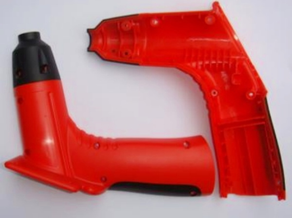
A molded housing brings wall sections, fasteners, appearance and assembly into one design.
Start with moldability
Six checks before the design is released
A useful design review connects the shape of the part to how it fills, cools and leaves the mold. Review these features together, using the intended resin and the actual assembly requirements.
01 / WALLS
Keep sections consistent
Abrupt thickness changes create regions that cool and shrink differently. Review heavy corners, pads and intersections; core out excess material where the function allows it. A thinner wall is only useful if the selected resin can fill it reliably.
02 / RELEASE
Design the draft direction
Draft lets a molded surface separate from the tool with less drag. Check walls, ribs, bosses and deep features in the intended opening direction. The appropriate angle depends on depth, texture, resin and the ejection arrangement, so one universal angle is not a specification.
03 / SUPPORT
Use ribs and bosses deliberately
Ribs and gussets can reinforce a wall without making the entire section thicker. Avoid heavy material buildups where supports meet the outer wall, and give screw bosses space, support and an appropriate hole design. Check the loaded assembly, not just the isolated CAD feature.
04 / TOOL MOVEMENT
Identify every undercut
Ask how each hook, side hole or thread will clear the steel. An undercut may require a side action, lifter, unscrewing mechanism or a revised feature. Review access and release early because additional tool movements affect construction, maintenance and the available molding approach.
05 / FLOW & APPEARANCE
Agree where the marks can go
A gate introduces resin; the parting line separates tool sections; ejectors release the part. Each can affect an important surface. Mark cosmetic and sealing areas, discuss acceptable gate vestiges and ejector locations, and review where flow fronts could meet.
06 / FIT & FUNCTION
Define the dimensions that matter
Identify the features that control assembly, sealing, motion or alignment. Provide datums, tolerances and an inspection method for those features. The mold dimensions and the finished molded-part dimensions are different considerations because the resin shrinks and responds to processing conditions.
Use guidelines to start a review, not to skip one
Wall thickness, draft, rib proportions and attainable tolerances depend on the material grade, part geometry and tooling concept. Final values should be reviewed for the actual part rather than copied from a generic chart.
Read the part as an assembly
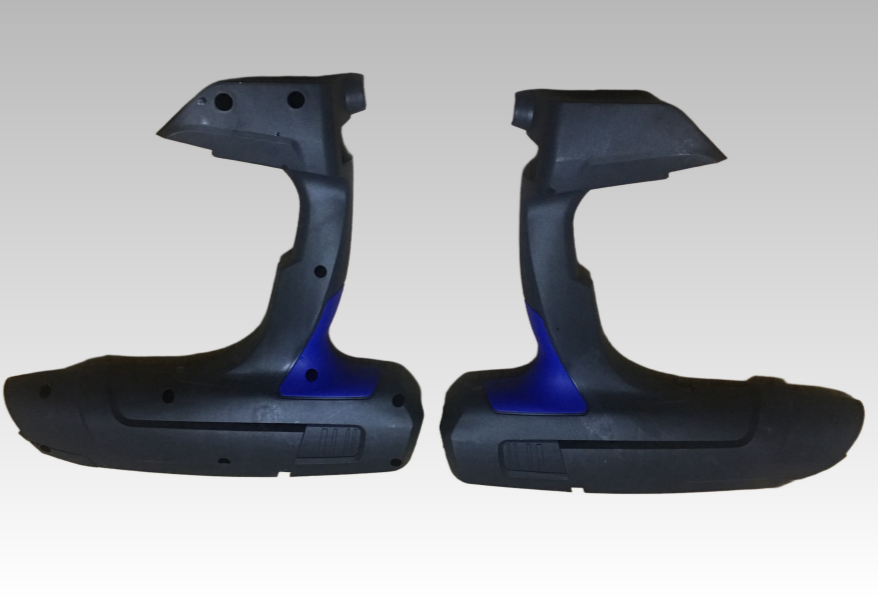
Housing halves make the relationship between internal supports and external surfaces visible.
One feature can create several requirements
A housing screw boss has to accept its fastener, carry the assembly load, release from the mold and avoid an unacceptable mark on the visible face. Review its wall, nearby ribs, screw engagement and mating clearance as one system.
For a grip or two-material component, also define which region provides structure, which provides touch or sealing, and how the materials must remain attached.
For clear components, separate cosmetic transparency from optical function. A cover may be judged under agreed viewing conditions; a lens or light guide may also need specified transmission, geometry or light-distribution measurements. Show the important surfaces and the checks that determine acceptance.
Prepare a reviewable design package
A CAD model shows the geometry. The following information explains what must be protected when the design is adapted for manufacturing.
Current model and revisionUse matching part numbers and revision identifiers on the model, drawing and request.
Critical drawing requirementsIdentify datums, fits, sealing surfaces, tolerances and the features to be measured.
Material and applicationName the proposed grade or explain the loads, temperature, chemicals and environment.
Appearance mapMark visible areas, texture or polish requirements, color references and acceptable witness marks.
Mating parts and assemblyInclude the interfaces, fasteners, inserts and checks needed to judge fit and function.
Open decisionsSeparate fixed requirements from features that may change during the design review.
Make changes traceable
Record the agreed design changes in a new revision and identify which earlier files it replaces. Review the affected fit, appearance and inspection requirements before treating the design as released for tooling.
Quick reference
Mold terminology
Use these short explanations during a part or tooling review. Open a term below, or follow the steel and hot-runner links to the Materials guide.
What is a plastic injection mold?
A plastic injection mold is a tool whose cavity and core surfaces form the part geometry. In thermoplastic molding, molten plastic enters the closed tool, cools sufficiently and is then released. The mold also needs systems for material delivery, temperature control, alignment and part removal.
Draft angle
Draft is the taper applied to a surface relative to its direction of release from the mold. It helps reduce rubbing and damage during ejection. Suitable draft depends on feature depth, texture, resin and the tooling arrangement; it should be reviewed alongside the functional shape.
Parting surface / line
The parting surface is the interface where mold sections meet. The parting line is its visible boundary on the molded part. Choosing that interface affects how features are formed and released, as well as the location of a witness line on visible or functional surfaces.
Plastic shrinkage rate
Mold shrinkage describes how a molded part becomes smaller than the cavity dimensions as the material cools and stabilizes. The expected change depends on resin grade, part geometry and processing conditions. Tool dimensions use an appropriate allowance; a single percentage cannot describe every material and feature.
Gating system
The gating or feed system carries molten plastic from the machine nozzle toward the cavities. A conventional cold-runner layout uses a sprue, runners and gates. Its layout influences pressure loss, filling balance and material usage, so it must be designed with the resin and cavity arrangement.
Gate types
A gate is the opening through which plastic enters the cavity. Options include edge or tab gates, tunnel gates and hot-runner gate arrangements. The choice affects filling, gate removal and the remaining mark. Selection depends on resin, геометрия, appearance requirements and the proposed production method.
Mold cooling
Cooling channels carry a temperature-control medium through the mold to remove heat and manage tool-surface temperature. Channel layout and fluid flow influence temperature differences and cooling consistency. The cooling plan should be considered with the cavity shape, resin and production cycle rather than added after the tool layout is fixed.
Ejection system
The ejection system applies the force needed to release the molded part after the tool opens. Ejector location and contact area affect how that force is distributed and where marks may remain. Review ejection together with draft, resin behavior, supporting geometry and cosmetic requirements.
Guiding system
The guiding system uses components such as leader pins and matching bushings to bring mold sections into alignment. These are mold components, distinct from the molding machine platens. Their fit and wear condition matter to repeatable registration of the cavity and core during repeated opening and closing.
Venting system
Venting features provide escape routes for air and gases displaced as plastic fills the cavity. Effective venting helps limit trapped gas, burn marks and incomplete filling. The vent layout should be considered with the filling pattern and the locations where air is likely to become trapped.
Slide / side-action
A slide is a movable mold component that can form a side hole or undercut and then withdraw so the part can be released. Its movement is commonly transverse to the main opening direction. Slides are one tooling solution; not every undercut requires the same release mechanism.
Surface finish
Surface finish describes the polish or texture specified for a mold surface and the resulting appearance expected on the part. Resin, color and fillers also influence that appearance. Identify the surfaces and finish reference, then agree how representative molded samples will be judged rather than relying on a broad word such as glossy.
Mold steels
Mold steels are selected for the job of each plate, cavity or core component. Wear, corrosion exposure, polishability and heat treatment can lead to different choices. See the Materials guide for steel families and the information needed to specify an exact grade.
A hot runner uses a heated melt-delivery system within the mold. Its gate arrangement, heating design and controls must suit the resin and application. The Materials guide compares open and valve gating, heating architecture, supplier examples and the interfaces that need to be specified.
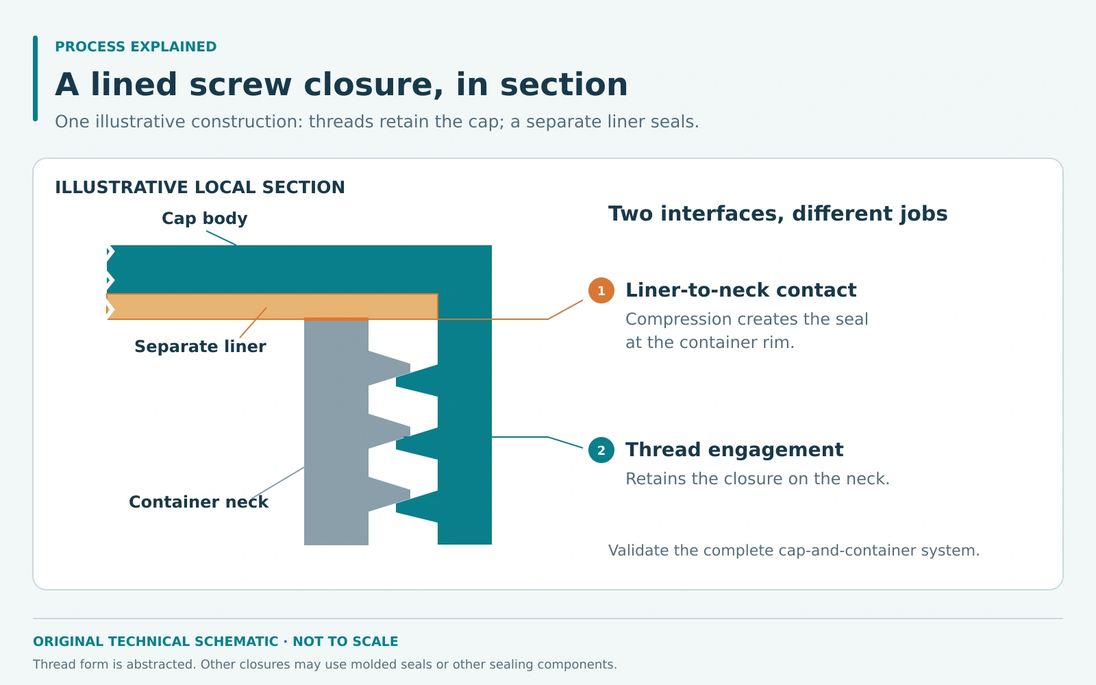
Cap molds must reproduce sealing and opening features consistently across every cavity. Learn how the injection cycle, thread-release method, охлаждение, and maintenance affect closure…
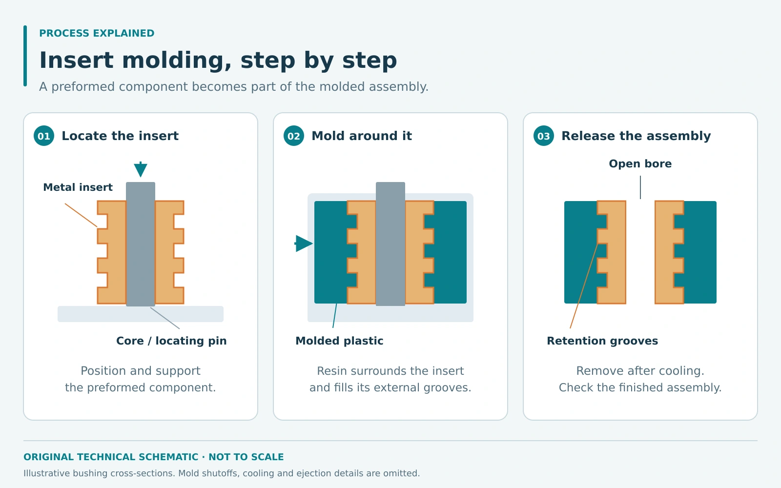
Вставное литьё сочетает предварительно сформированные компоненты с литьевым пластиковым корпусом. Это руководство объясняет процесс, как механическая фиксация помогает пластику и металлу работать вместе,…
Двухкомпонентное литьё сочетает два материала или цвета в согласованной последовательности литья. Explore how material compatibility, substrate support, shut-off design, and differential shrinkage…