


An unscrewing mold forms a plastic thread and releases it through controlled rotation. The method is commonly used for internal threads in caps, connectors, and fittings when simply pulling the part off a core would damage the thread.
The release mechanism must work with the thread geometry, resin, and surrounding part design. Specifying those requirements early helps avoid a tool that fills successfully but struggles to demold consistently.
How an unscrewing mold works
- Position the thread-forming components. The threaded core and other moving elements return to their molding positions. The mold closes and clamps before injection.
- Inject, pack, and cool. Resin fills the cavity and forms the thread profile. The part cools sufficiently to withstand the forces applied during release.
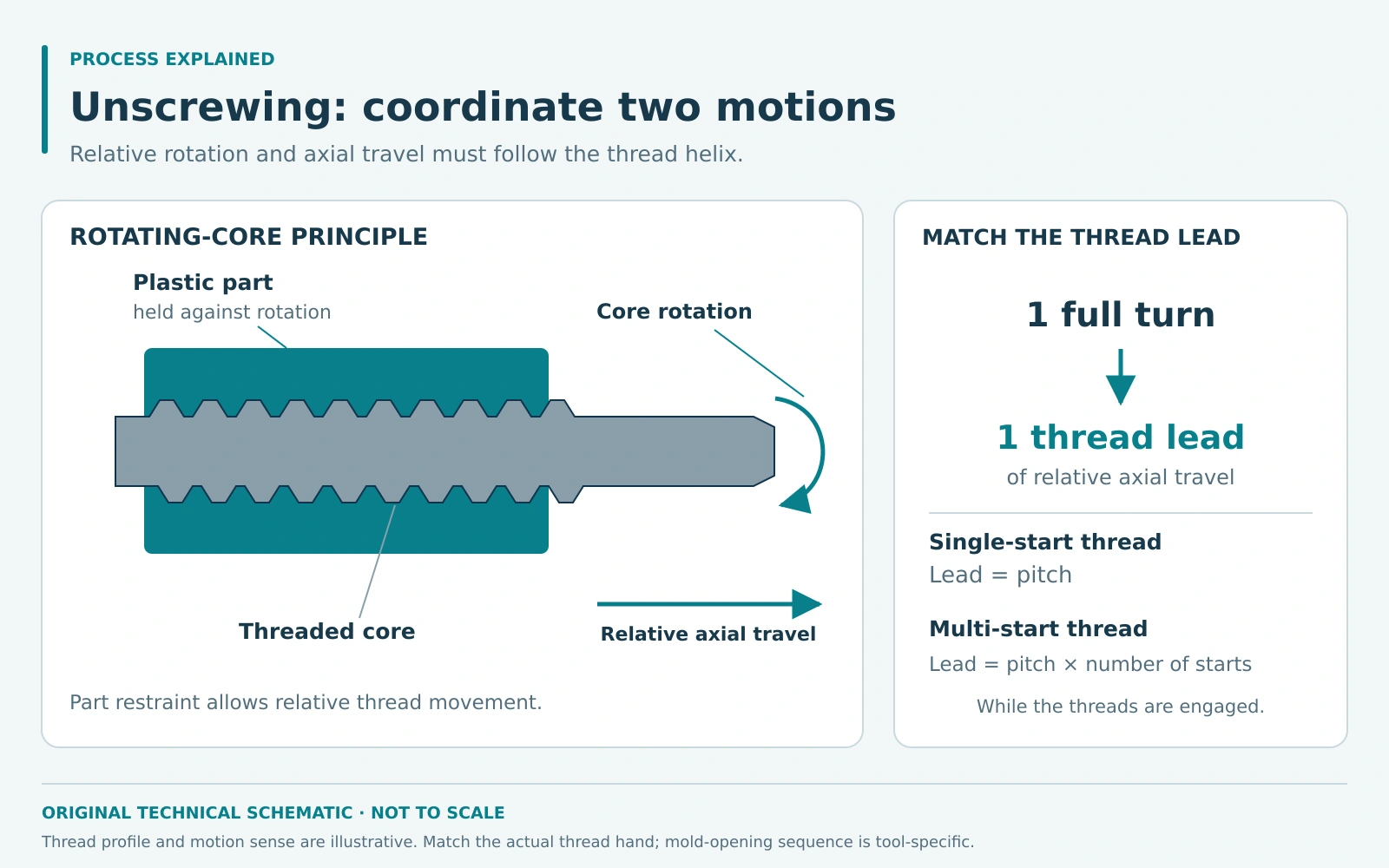
- Restrain the part and unscrew. In a rotating-core arrangement, the part is held against rotation while the core turns. Relative axial movement between the core and part follows the thread helix.
- Complete release and removal. Once the thread is fully disengaged, the ejection or handling system removes the component. The mechanism then resets for the next cycle.
The timing of unscrewing relative to mold opening depends on the tool design. Some mechanisms use the opening movement as their drive; others use a separately controlled drive. There is no single opening sequence that applies to every unscrewing mold.
Match rotation to thread lead
Thread lead is the axial travel over one complete revolution. For a single-start thread, lead equals pitch. For a multi-start thread, lead equals pitch multiplied by the number of starts, as explained in Sandvik Coromant’s threading guide. The release motion must match lead, with sufficient rotation and clearance to disengage the entire molded thread.
Part restraint is equally important. If the part rotates with the core, the thread cannot release as intended. The tool may use suitable part geometry or an anti-rotation feature within the stripping arrangement. DME’s hydraulic unscrewing guidance illustrates coordinated rotation, stripper movement, and anti-rotation components.
Drive selection must account for release torque, travel, space, and cavity layout. Hydraulic, mechanically driven, and servo-electric arrangements are available. Servomold’s unscrewing systems overview shows how controlled rotary motion is applied to internal-thread demolding.
Benefits and limitations
Molding the thread directly can remove a separate tapping or machining operation. Controlled unscrewing can preserve a thread profile that would be damaged by forced stripping, while an automated mechanism supports repeated production.
However, an unscrewing mechanism adds moving components, toolmaking work, and maintenance. Rotation and release travel can also affect the cycle. The resin’s shrinkage, the thread surface, and the temperature at release influence how tightly the molded part grips the core.
Thread accuracy still depends on the tool, material, and process. Define how it will be checked with the mating component, gauges, or other agreed methods. For a sealing connection, test the sealing function separately from whether the thread assembles.
Consider alternative release methods
Some external threads can be formed using split tooling. Certain internal threads can use collapsible cores, and selected flexible parts with suitable thread geometry may permit stripping. These options have their own geometric and material limits.
Review the alternatives before committing to an unscrewing mechanism. Covestro’s part and mold design guide discusses thread and undercut release methods and the added complexity associated with moving mold components.
Thread release is a coordinated motion problem: rotation, axial travel, and part restraint must work together. A suitable unscrewing mechanism protects the molded profile while allowing the part to leave the tool consistently.